Product
English > SVP-01-G
Parallel Generator
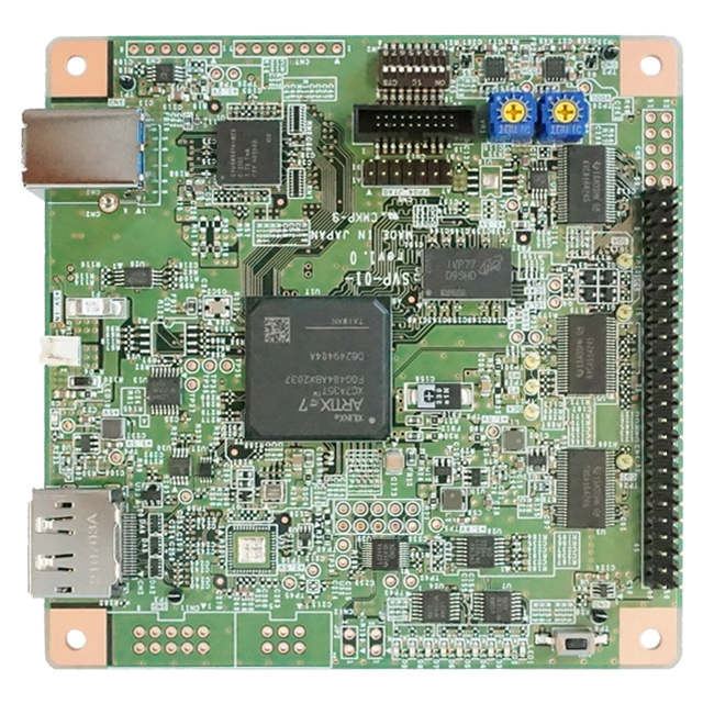
SVP-01-G■Overview
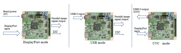
 The parallel generator board SVP-01-G converts video signals input via USB3.0 or DisplayPort to parallel interface.
This board can output recorded video to an image processor like images from a camera module or a CMOS image sensor, so it can be used as a camera emulation board. Computer Graphics images that are saved on a PC can also be used. It is helpful for developing image processors, even when recording on site is difficult and when sensors are under development or unavailable.
Output timing such as blanking area and frame rate can be set as desired for flexible camera emulation.
■ Characteristics
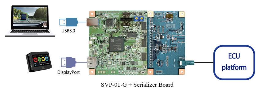
■ Configuration Example
- DisplayPort input and USB3.0 input are mode switching type, so you can use only one mode all at once.
- By using HDMI to DisplayPort conversion, it is also possible to connect to a PC or other HDMI recording/playback device.
■Specification
| Table Item | Specification | Remarks | |
|---|---|---|---|
| Video input interface | USB3.0 (Windows) DisplayPort 1.1a |
ー | |
| DisplayPort 1.1a input details | Raw Bit Rate = 2.7Gbps/Lane x 2L Pixel format : RGB24 (24bpp RGB) |
Dual-Mode (DP++) : Unsupported HDCP : Unsupported |
|
| Video output interface | Parallel video signal | Supports FPD-Link III, GMSL as serializer | |
| Output resolution | Up to 8190x4095 pixel | In the case of 8bit is 4094x4095 | |
| Supported sync signal | VSYNC, HSYNC, Pixel Clock | Supports Embedded SYNC(BT.656), Data Enable |
|
| Clock rate | ~ 150 MHz | ー | |
| Supported pixel formats | YUV422(8bit) / RGB24 | ー | |
| Output bit width | 8 / 16 / 24 / 32 bit | Use GPIO pins for 24 and 32 bit | |
| Other interfaces | I2C | Frequency:max. 400kHz | Only mastar, voltage level follows VDDL Device address 7bit |
| GPIO | 16bit is available by implementing connector CN5 | Voltage level follows VDDL GPIO + Image input = 32bit max. |
|
| Power supply | Board power (Input) | USB bus power / Dedicated 2pin connector | Supply voltage:+5V(4.75-5.5V) |
| Target side power (Output) | VDDL = 1.8 ~ 3.3 V VDDH = 1.2 ~ 3.6 V |
VDDL:IO power supply setting VDDH:Power supply for connection board |
|
| Other functions | Reset signal output Clock signal output FSYNC signal input |
ー | |
| Interface connector | 50 + 10 pin (2.54mm pich pin header) | 10pin is added for 24bit or 32bit input | |
| FPGA | Artix-7 (XC7A35T) | ー | |
| Frame memory | 256MByte (DDR3-SDRAM) | ー | |
| USB3.0 chip | Cypress EZ-USB FX3 | ー | |
| Dimensions | Length x Width x Height = 101.6 x 101.6 x 25.7 (mm) |
Including spacer (10mm) in height | |
| Attached software Windows |
Video display software | NVFilePlayer SVOGenerator |
ー |
| I2C control software | SVMCtl | Including SV board update application | |
| Supported SerDes boards of our company | DS90UB913A, MAX96701, MAX96705, MAX96707 etc., |
ー | |
【SV series common specifications】
Application software:SVOGenerator & SVOCtl, Test pattern output function
■ Design Documents
■ Full Package Download
■ Application
CMOS sensor & Camera module emulator, Picture playback, DSP Verification, Evaluation
■ Application Areas
Automotive / transportation equipment, medical testing / analysis / measurement, IT / information / communications, software, education / research institutions, and so on.
■ Old Model
Notes: Product names and company names are trademarks of each companies.
These data may be changed without a preliminary announcement for specification change.