For NVIDIA's DRIVE PX2/AGX
Camera Emulation SystemAI in-vehicle computing platform made by NVIDIA company
NVIDIA's DRIVE PX2/AGX is a scalable computing platform for autonomous vehicles.
It can process data from cameras, radar and lidar to recognize the surrounding environment, estimate the position of the vehicle according to a map, and plan and lead the safe routes. It supports safety functions for such as autonomous driving, in-vehicle functions, and driver monitoring.
In the automotive industry, the establishment of autonomous driving technology is urgently needed, so DRIVE PX2/AGX has been developed to realize a platform compatible with an expandable architecture from [level 2] driver assistance to [level 5] fully autonomous driving.
Development progresses for realizing safe autonomous driving using AI technology with deep learning.
What is the camera emulation system for DRIVE PX2/AGX?
The input type from the camera to DRIVE PX2/AGX is GMSL/GMSL2. Therefore, there is no way to verify the image but to connect the camera and input the image to it in real time to debug.
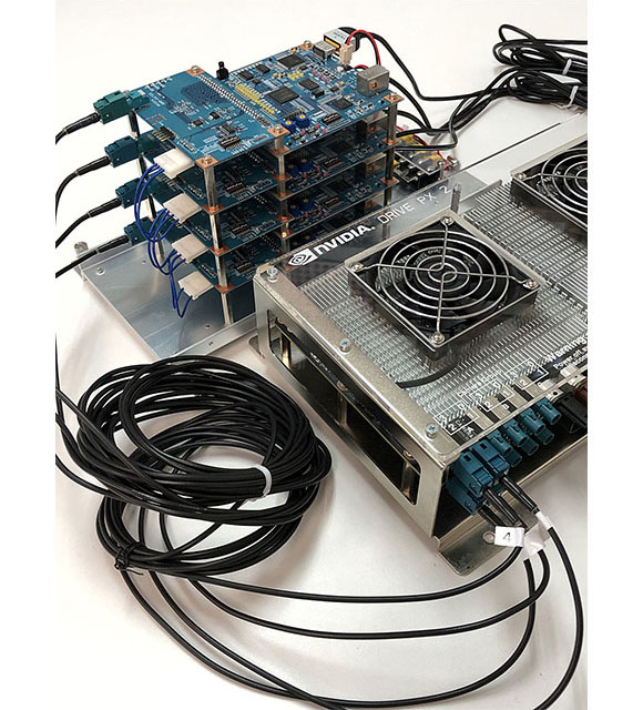
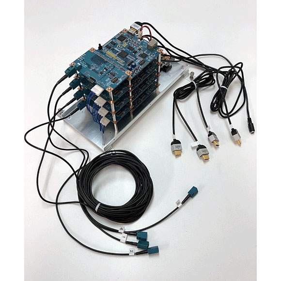
So, by using our parallel generator SVO and GMSL serializer board, it is possible to convert HDMI (which is easy to output from PC) to GMSL, and to input to DRIVE PX2/AGX instead of the camera.
Since the real-time rendering video generated by the simulator can be directly input to DRIVE PX2/AGX, you can use the virtual environment. As a result, the amount of operation in the actual vehicle can be reduced, making it economical and efficient. Also, you can test and verify hardware and software for autonomous driving safely and accurately.
Build a virtual simulation environment for autonomous driving
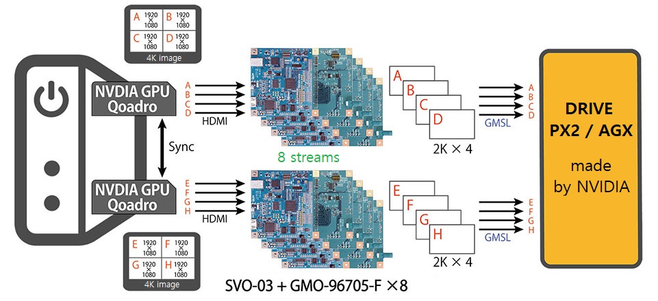
* The above diagram is an example. It will be changed depending on connected items and situations.
This figure shows the configuration of the camera emulation system for DRIVE PX2/AGX.
The video source corresponding to the effective pixels of each camera is placed on the 4k size monitor screen, and each video is output from the PC via HDMI using the cutout function of the graphic board. The video is converted to the resolution including the embedded line and the same timing as the PCLK of the camera, and input to DRIVE PX2/AGX in GMSL format.
This enables camera emulation equivalent to a maximum of 8 cameras.
SVO-03 + GMO-96705
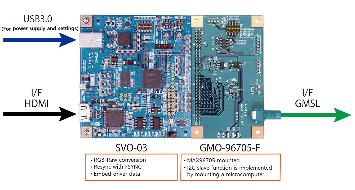
This figure shows the operation of SVO-03 and GMO-96705-F.
PThe image from the PC is input from the graphic board made by NVIDIA via HDMI. At this time, the image signal RGB24 is converted to RAW 12bit format according to the Bayer format of the camera.
Also, the HDMI input from each board is synchronized using the Sync function between graphic boards made by NVIDIA. Resync processing is performed that the video output to DRIVE PX2/AGX is synchronized when the FSYNC of each board has the same timing.
In addition, the data that allows the driver on the DRIVE PX2/AGX side to operate properly is embedded in the embedded line above and below the active data of the image prepared instead of the camera image.
The GMO-96705-F attached to the SVO-03 converts the signals to the GMSL format, in MAX96705 serializer IC made by MAXIM. And, in order to support the back-channel communication sent from the Deserializer IC on DRIVE PX2/AGX, it is mounted a PIC microcomputer and implements the I2C slave function, so it can respond the command from DRIVE PX2/AGX to a camera.
Parallel generator SVO-03
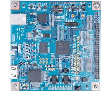
SVO-03 is a board for converting video signals input via USB 3.0 or HDMI to parallel signals. USB mode and HDMI mode can be switched with Dip switch.
In USB mode, it converts the uncompressed “.avi file” or “.frm file” saved on the PC into a parallel video signal and outputs it. The output pixel format supports YUV4:2:2 8bit, Raw10, Raw12, RGB24.
In HDMI mode, it converts RGB24 signal input from HDMI connector to RAW 12bit or YUV422 8bit and outputs it. Since it operates as an HDMI receiver, EDID (Extended Display Identification Data) settings are required for notice the HDMI transmitter of the resolution and timing supported by the receiver.
GMSL Serializer board GMO-96705-F
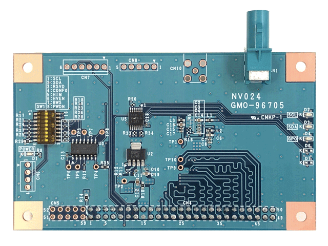
GMO-96705-F is an option board for SVO-03, mounted MAXIM's serializer IC MAX96705. This board is for converting the video signals input in parallel format to GMSL signals. It is mounted a PIC microcomputer (PIC16LF1825) for FAKRA standard coaxial output connector and I2C emulation of the camera, and it is possible to operate including I2C command response.
It can be applied to emulation of GMSL camera by combining with SVO-03 board.
*Product names and company names are the trademarks of each companies.
*This document may be changed without notice because of specification changes.