Product
English > SVP-01-U
Parallel Image Monitoring Board
SVP-01-U■ Overview
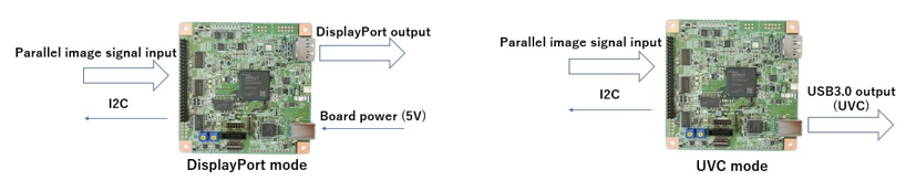
 The parallel image monitoring board SVP-01-U has parallel video input and DisplayPort or USB3.0 output. You can capture, record and display video signals of the parallel interface.
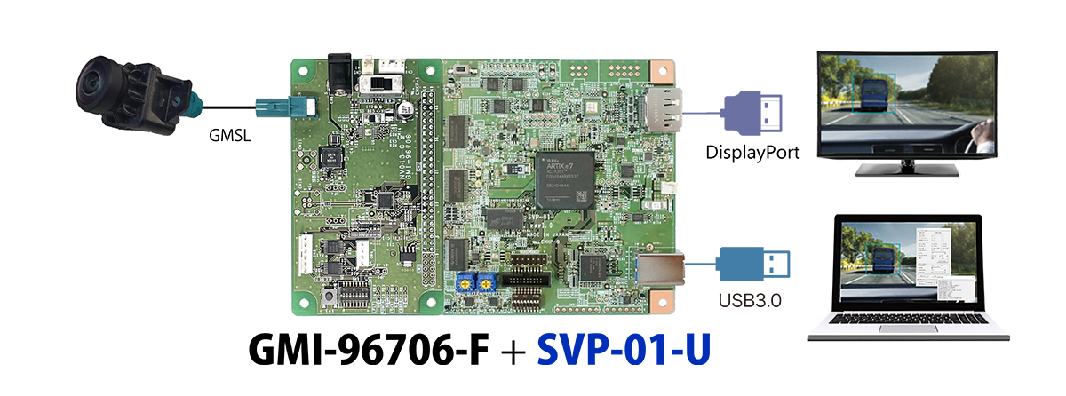
This board has 2.54mm pitch pin header connector for the interface to camera module. We have developed many deserializer boards that can be directly connected with this board, so it is also possible to connect with automotive cameras.
Powering this board is basically via a USB 3.0 connector, but you can use a USB-AC adapter instead in DisplayPort mode.
In addition, this board is compliant to UVC (USB Video Class), so it can be worked on not only our capture software but also the third party capture software that supports UVC devices. This board has I2C interface for setting of image sensors and Ser/Des devices. The capture function can work on Windows and Linux.
■ Characteristics
• Supports up to 1080p/60fps input
• 2 type variable voltage outputs including 1.8-3.3V IO voltage
• I2C, GPIO bus control function
• USB3.0, DisplayPort output
• USB bus power operation
• Inter-board sync signal connector (optional)
• Supports 1.9Gbps band in-vehicle deserializer
• 2 type variable voltage outputs including 1.8-3.3V IO voltage
• I2C, GPIO bus control function
• USB3.0, DisplayPort output
• USB bus power operation
• Inter-board sync signal connector (optional)
• Supports 1.9Gbps band in-vehicle deserializer
■ Configuration Example
■Specification
| Table Item | Specification | Remarks | |
|---|---|---|---|
| Video input interface | Parallel video signal |
IO voltage = 1.8-3.3V Supports FPD-LinkⅢ, GMSL, GVIF2 as deserializer |
|
| Video output interface | USB3.0 (Windows, Linux, UVC Driver) DisplayPort 1.1a (720P-60 fps / 1080P-60 or 30 fps) |
It is also possible to work with USB2.0(HS) Resolutions other than those on the left are individually supported When conenct to DP-HDMI converter, use active type |
|
| Input resolution | Up to 8190x4095 pixel | In the case of 1920x1080, about 60 fps In the case of 1280x720, about 120 fps |
|
| Output bit rate | (UVC mode) within 3.0 Gbps (DisplayPort mode) within 4.3 Gbps |
In the case of 1920x1080 (UVC mode) about 80 fps In the case of 1920x1080 (DisplayPort mode) about 60 fps |
|
| Supported sync signal | Vsync, Hsync, Pixel Clock | Supports Embedded Sync(BT.656), Data Enable Signal polarity can set from software |
|
| Clock rate | ~ 150 MHz | ー | |
| Supported pixel formats | YUV422 8bit / RGB24 / Raw | ー | |
| Input bit width | 8 / 16 / 24 / 32 bit | Use GPIO pins for 24 and 32 bit | |
| Other interfaces | I2C | Frequency:100 / 200 / 400 kHz | Voltage level follows VDDL |
| GPIO | Up to 16bit, IN / OUT direction control every 8 bits | Voltage level follows VDDL GPIO + Image input = 32bit max |
|
| Power supply | Board power (input) | USB bus power / Dedicated 2pin connector (5V) | ー |
| Target side power (output) | VDDL = 1.8 ~ 3.3 V VDDH = 1.2 ~ 3.6 V 3.3 V output available |
VDDL:IO power supply setting VDDH:Power supply for connection board |
|
| Other functions | Test pattern output function Image clipping function |
ROM startup:Function to automatically transmit SerDes setting file (I2C) | |
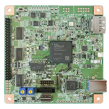
| Interface connector | 50 + 10 pin (2x25/30 2.54mm Pin Header) | 10pin is added for 24bit or 32bit input | |
| FPGA | Artix-7 (XC7A35T) | ー | |
| Frame memory | 256MByte (DDR3-SDRAM) | ー | |
| USB3.0 chip | Cypress EZ-USB FX3 | ー | |
| Dimensions | length x width x height = 101.6 x 101.6 x 25.7 (mm) |
Including spacer (10mm) in height | |
| Attached software Windows |
Video display software | NVCap | ー |
| I2C control software | SVMCtl | Including SV board update application | |
| Supported SerDes boards of our company | DS90UB914A、DS90UB934、MAX9272、 MAX96706 etc., |
ー | |
Application software:NVCap&SVMCtl, Test pattern output function, Image clipping function
■ Design Documents
■ Full Package Download
■ Application
Display video signal of camera modules or CMOS sensors to DisplayPort monitor,
Around view development, Simultaneous monitoring of multiple sensors.
Around view development, Simultaneous monitoring of multiple sensors.
■ Application Areas
Automotive / transportation equipment, medical testing / analysis / measurement, IT / information / communications, software, education / research institutions, and so on.
Notes: Product names and company names are trademarks of each companies.
These data may be changed without a preliminary announcement for specification change.